Key Matrix
Matrix Definition
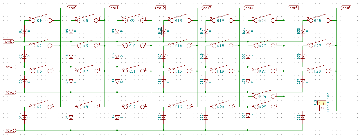
Most keyboards use a matrix of columns and rows to scan each key. You will need to refer to the keyboard schematic to identify how many columns and rows your keyboard uses for it's scanning matrix. The scanning matrix may differ from the keyboard layout. For example, a 4x12 matrix uses 16 GPIOs and allows for 48 keys to be scanned. A 8x8 matrix also uses 16 GPIOs but will allow 64 keys to be scanned.
Next, we need to identify how each row and column are mapped to the microntroller on board of the nRF52 module you use. Since most DIY keyboards use the Arduino Pro Micro as its controller, we are using such an example.
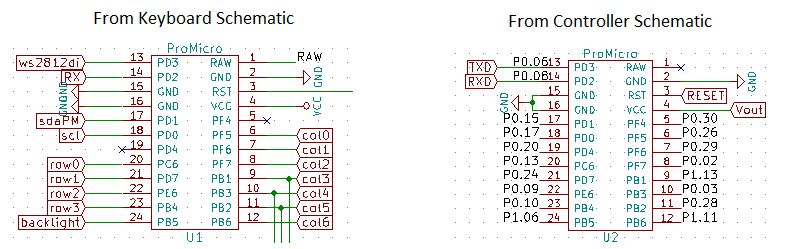
With the information from both the keyboard and controller schamatics, we can map each row and column to the GPIO and define the configuration needed.
Test Program
import board
import keypad

# Switch Matrix Setup.
keys = keypad.KeyMatrix(
    row_pins=(board.P1_11, board.P0_03, board.P0_28, board.P1_13),
    column_pins=(board.P0_02, board.P0_29, board.P0_30, board.P0_26),
    columns_to_anodes=True,
)


while True:
    key_event = keys.events.get()
    if key_event:
        print(key_event)
Make sure you are connected via a serial connection to the controller. (Connect to REPL) By pressing and releasing each key, you will see the press and release events as well as which key number generated the event.
Test each key and validate that they each work. If none work, change columns_to_anodes and test again. If a specific row or column do not work, verify if the GPIO configured is correct.